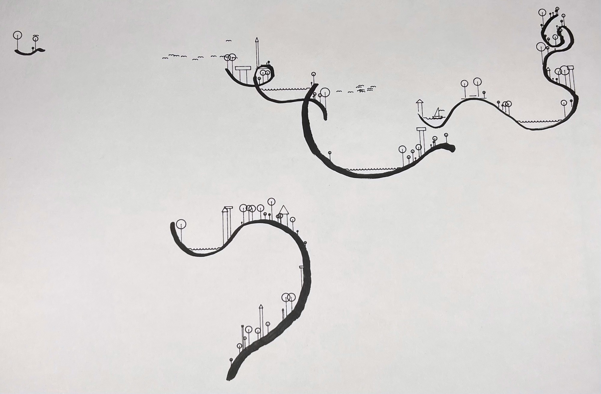
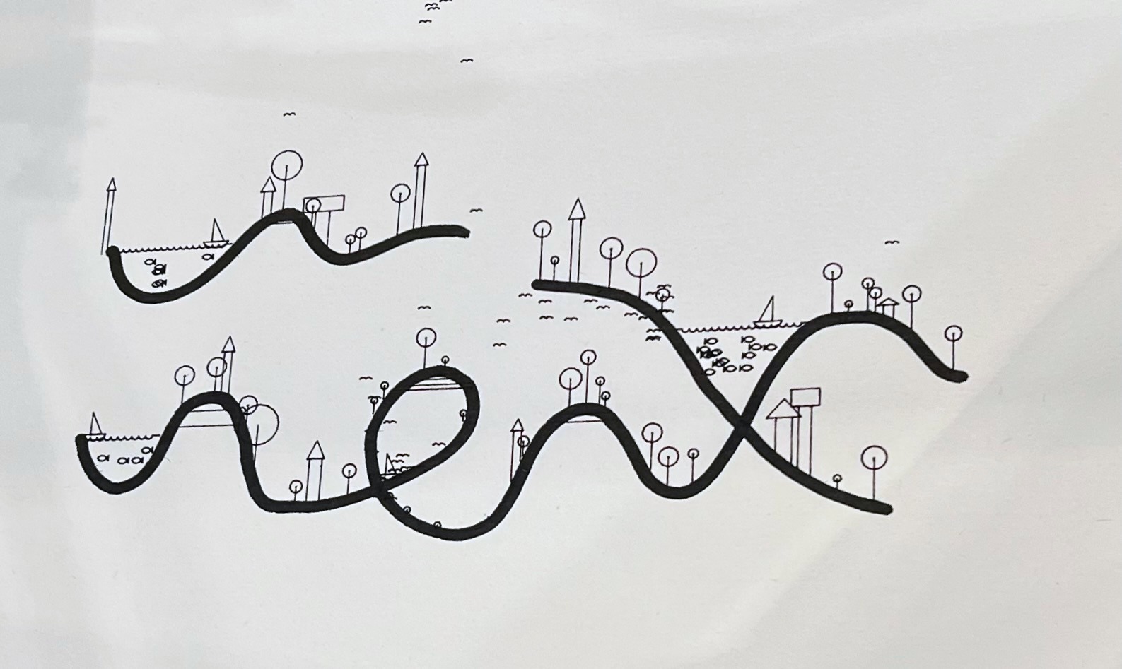
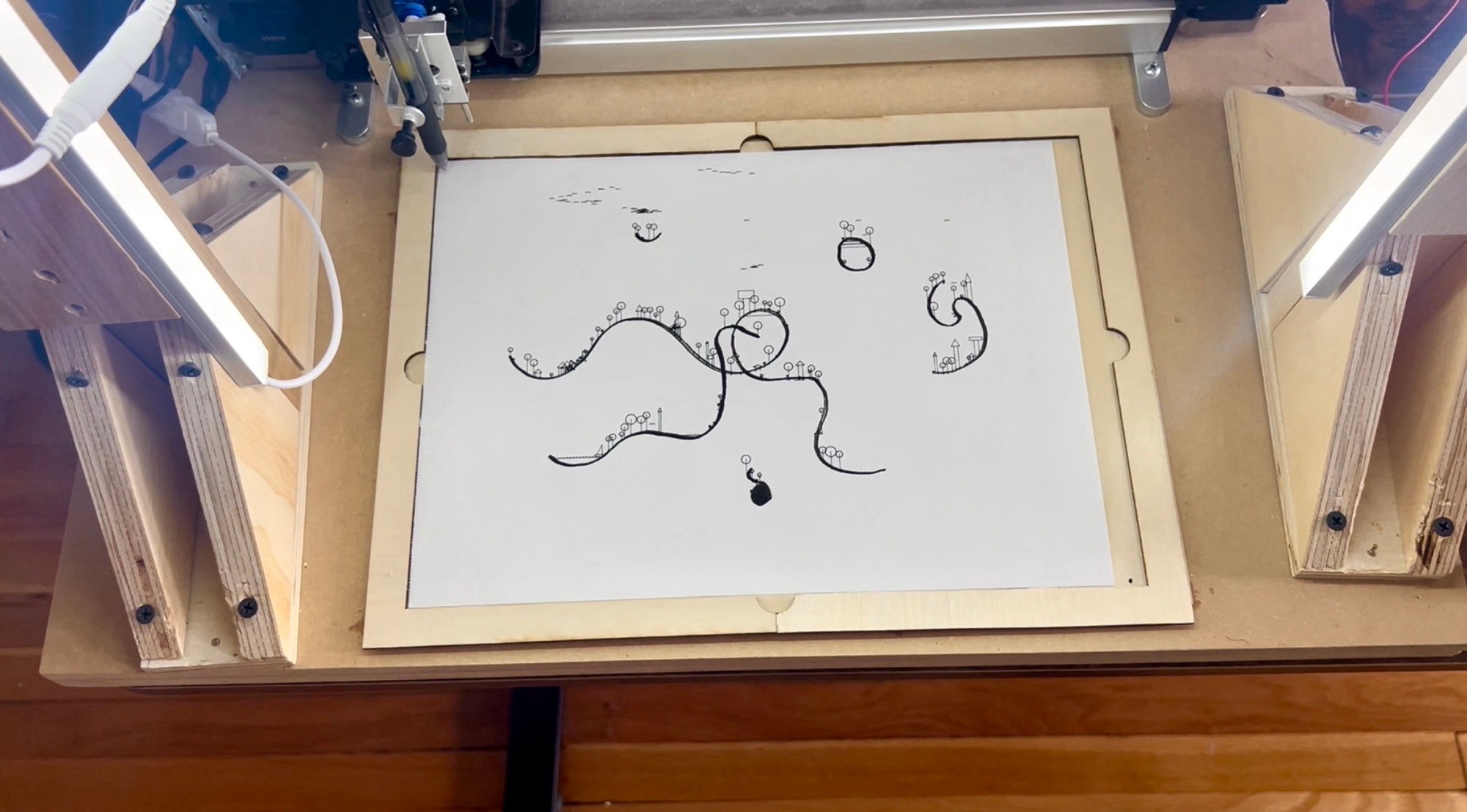
Collaborative Drawing Machine, 2025
Python, OpenCV, Axidraw
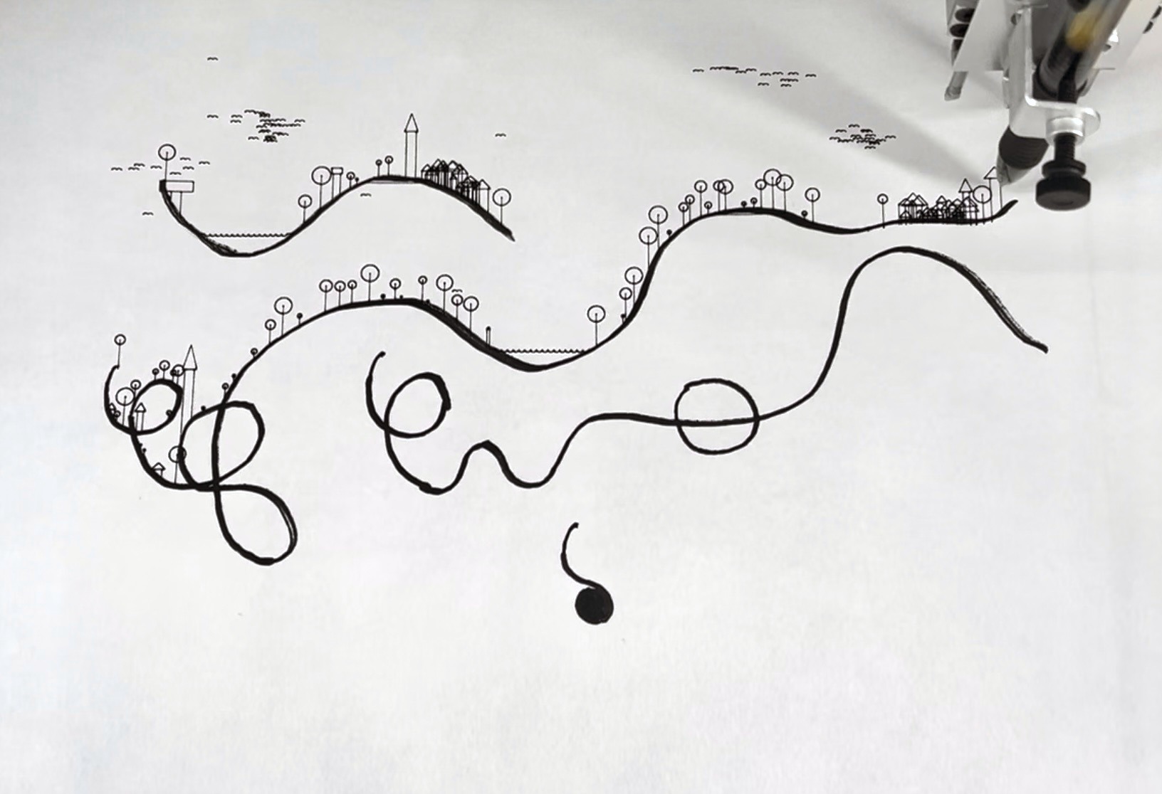
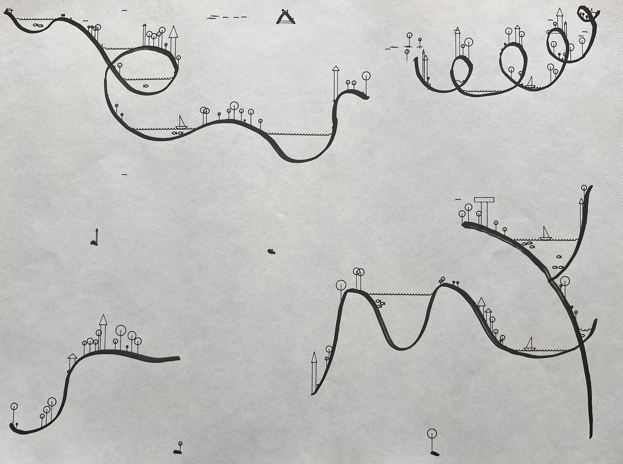
Interactive exhibition: Pen and paper drawings created through the collaboration of human and machine
Exhibited at the Tomayko Foundation, May 2025
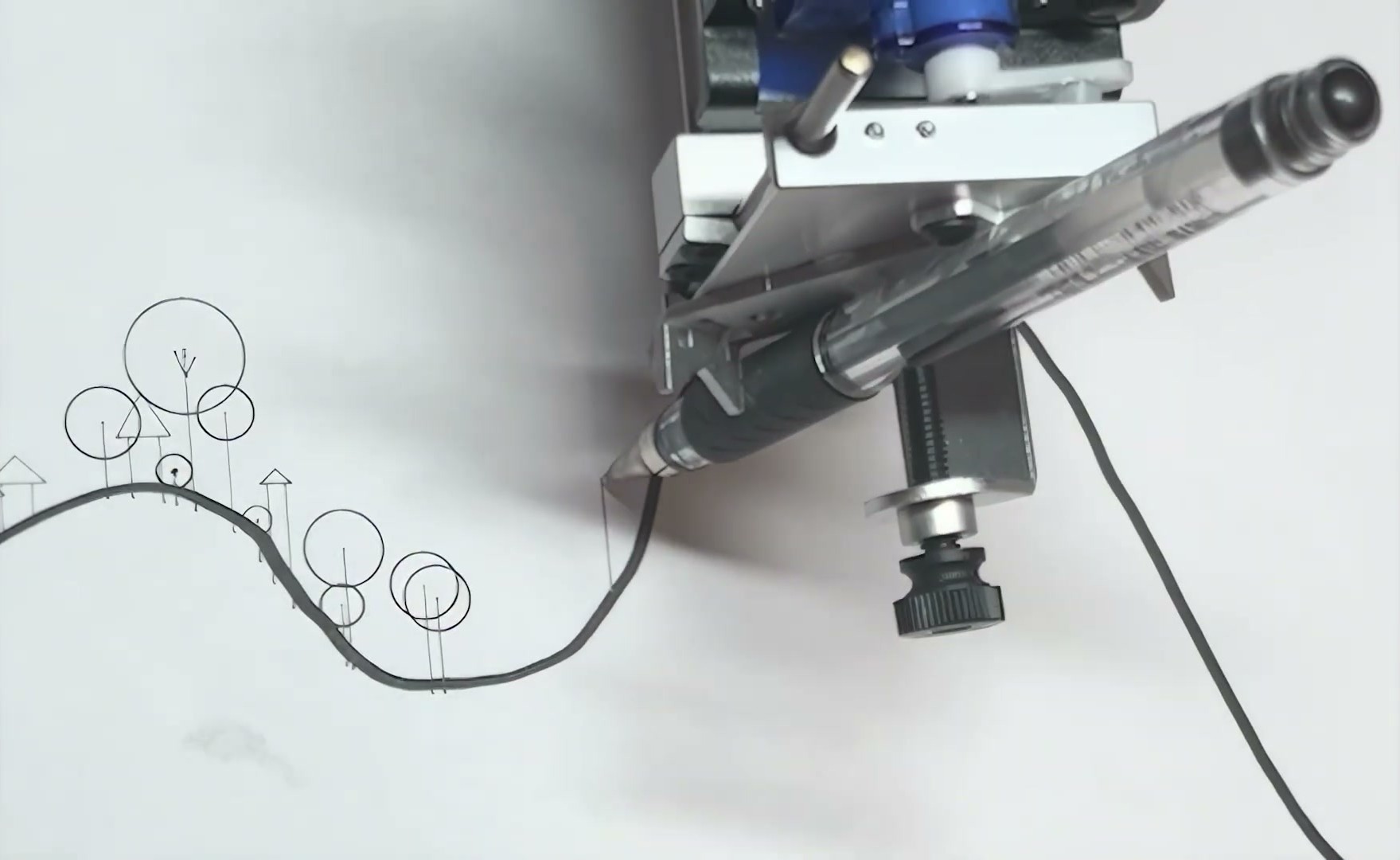
Creating this piece began by questioning my assumptions about how humans and technology collaborate to create art. Humans are often assumed to be the source of creativity, and technology works mindlessly to realize the human’s vision. But technology is inherently just as creative as a person - for example, a computer is certainly much more creative at guessing random numbers. So, how could I reverse these roles? In the Collaborative Drawing Machine, a person draws lines on a blank canvas, and the machine creatively reimagines these lines as a landscape.
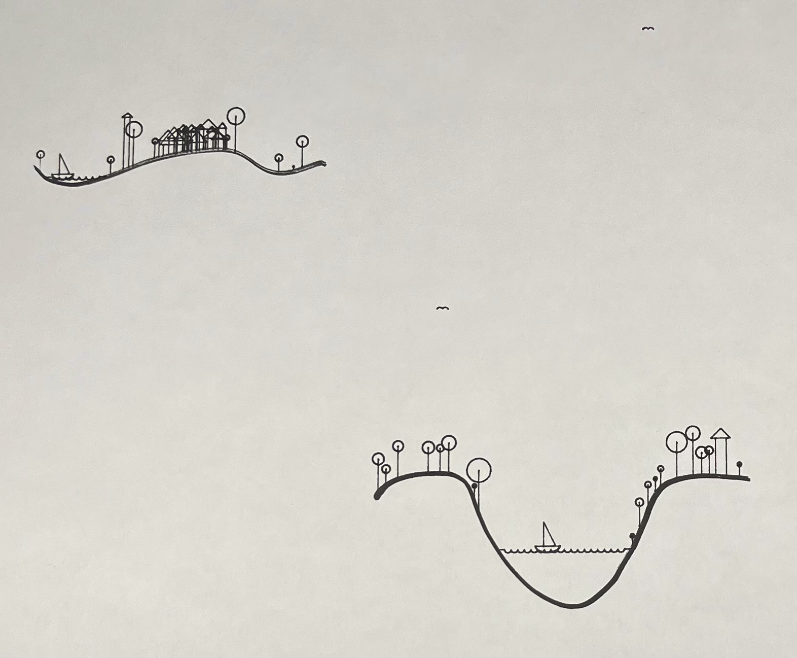
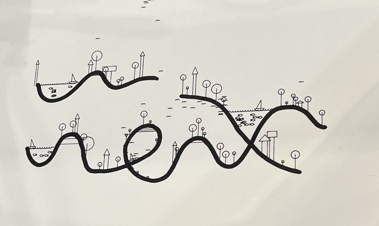
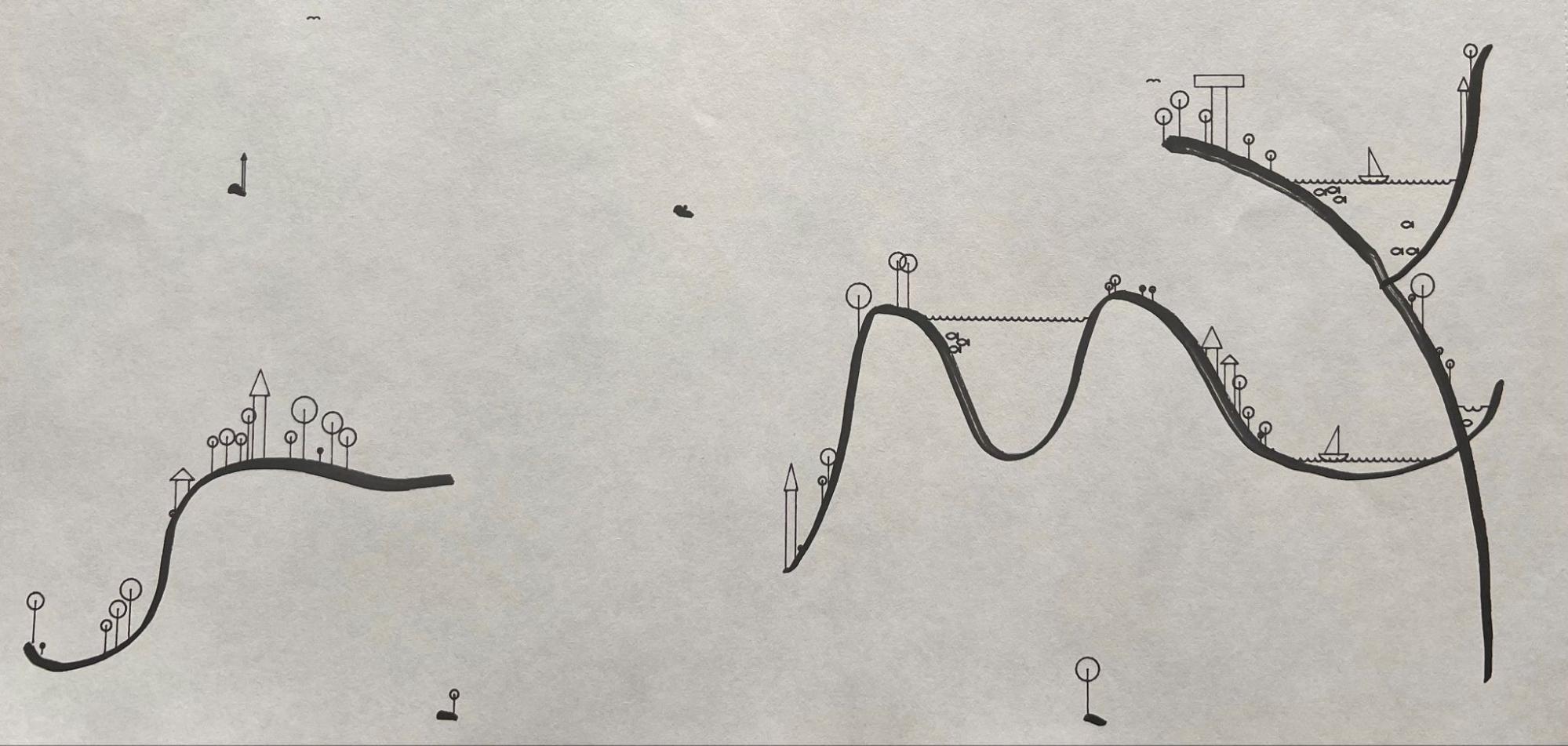
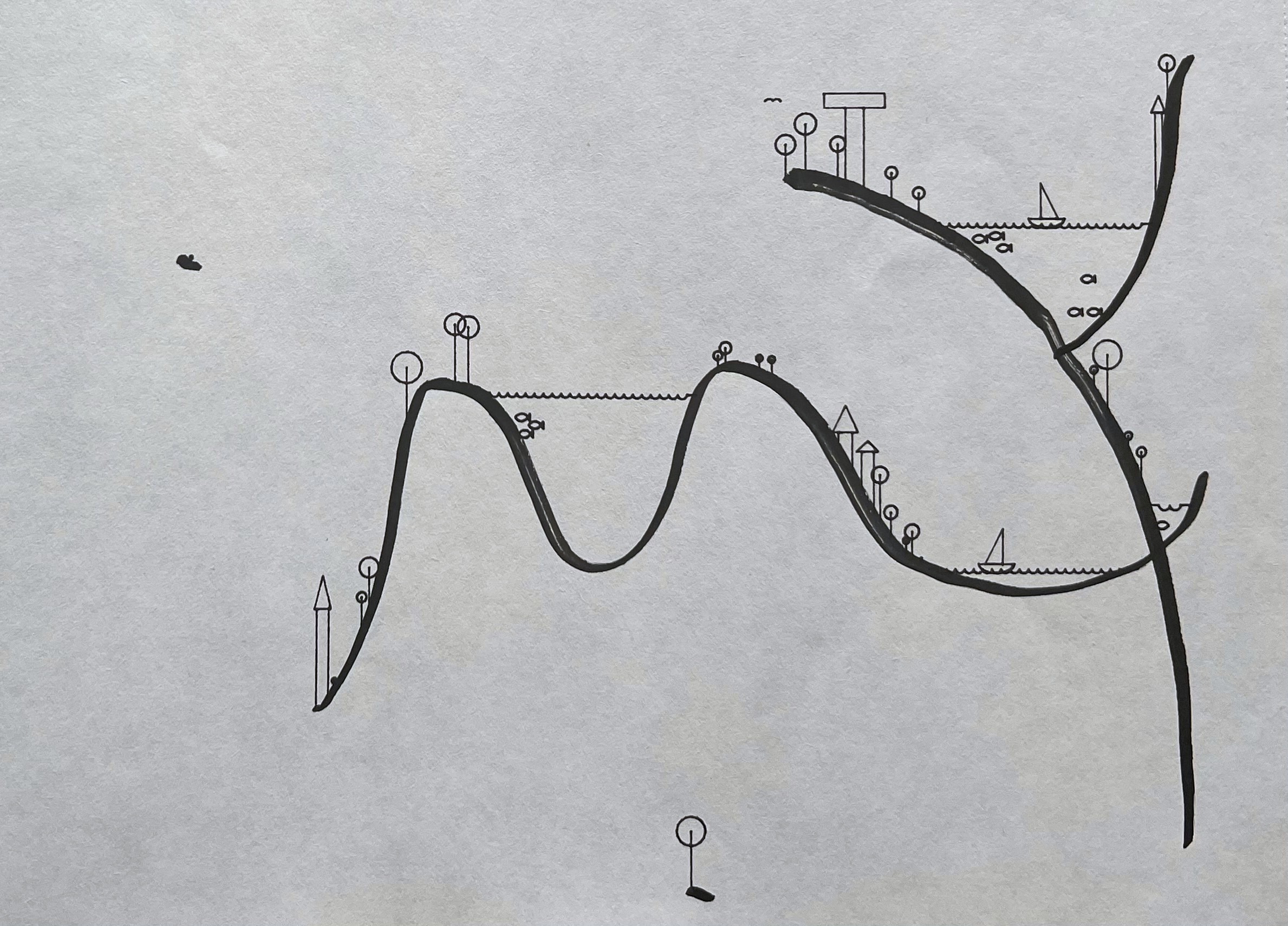
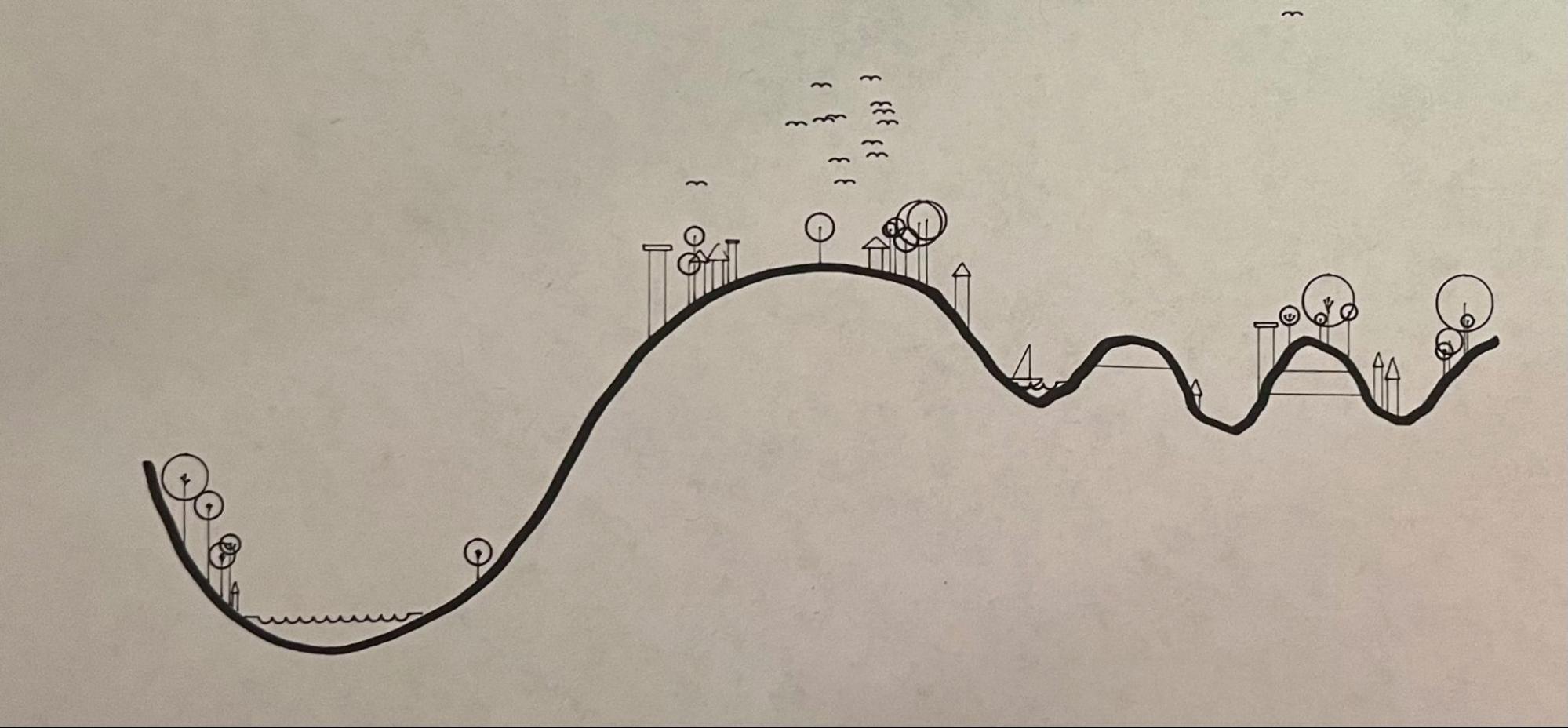
This process embodies collaboration by allowing users to consider non-human agents as creative equals. OpenCV image processing is used to determine the location of the Axidraw head and the line drawn on the paper. The contour is parsed internally, and my algorithm nondeterministically places features such as birds, houses, trees, towers, lakes, and boats upon the contour to turn the lifeless line into a tiny, floating world.
The First Prototype
February 2024
The project began in 2024 in Golan Levin’s Drawing with Machines course at Carnegie Mellon, where the very first prototype was presented as a simple weekly assignment on February 2nd. Even at that scale, the central idea was already in place: a person draws a line freely, and a machine reinterprets it as a landscape.
My ambition for the assignment was to build literally the core functionality of what would become the final project - a person draws the line, and the machine adds doodles directly into it. I had to abandon that in-place approach after realizing how difficult aligning a human drawing with the pen plotter would be. (Foreshadowing for a great deal of trouble further down the line.)
Instead, the participant drew a line, and then on a separate piece of paper the Axidraw redrew that original line plus its doodles.
Detecting the line
This worked by taking a photograph of the original hand-drawn version and then using a deliberately simple algorithm to find the line inside it: look through every vertical column of pixels, and add the single darkest pixel in that column as a vertex in the detected line.
That imposed two requirements on whatever the participant drew. First, exactly one y for every x - no overhangs and no doubling back, since the algorithm had no affordance for finding two separate dark marks in one vertical column. Second, a y for every x - the line had to extend from one end of the image to the other, because even in columns the line never reached there would still be a “darkest pixel” somewhere on the page, perhaps a mote of dust or a shadow, and it would be added as a vertex anyway.
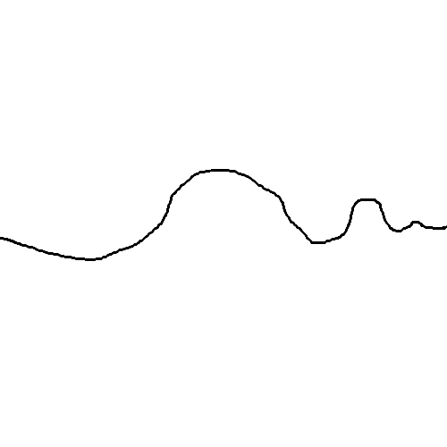
So in essence, each x value across the image had to correspond to exactly one y value on the line, which is equivalent to the vertical line test definition of a function. Per that test, this would be a valid line:
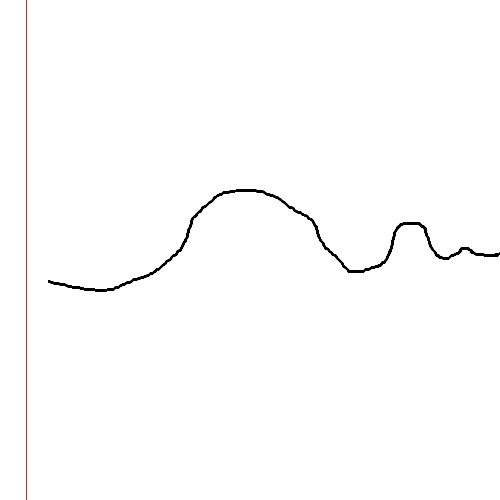
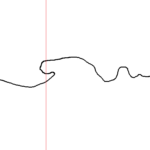
While these would not. The first fails because the line stops short of the frame’s edge, leaving columns with no line in them at all; the second fails the vertical line test itself, because the hook doubles back and gives one x value two y values:
Limitations
This had a lot of limitations. Being restricted to drawing functions is the obvious one, but it also meant being extremely careful about the lighting the photograph was taken in. Shadows could easily overwhelm the line. Just as dangerously, if either end of the line was in frame, the drawn line no longer passed the vertical line test relative to the image, causing chaos near the edges. And if the photograph was rotated at all, some of the more vertical parts of the line could tip just past vertical into an overhang, failing the same test and making the line processing go wonky.
Drawing on two separate sheets removed the alignment issue entirely, since the Axidraw was redrawing the participant’s line using its own internal coordinate system. But in my opinion it also dramatically weakens the core idea of a human-machine creative collaboration, because the collaboration is not in place - each collaborator has their own sheet of paper, and the two never physically meet on the same page.
All of this together shows how high-friction creating a collaboration was at this early stage, and how far it was from the seamless exchange I was going for. It rather makes you wonder why the human-drawn line couldn’t simply be made digitally: that would dodge all the jank created by the line detection system, and it would be no more disparate than two separate sheets of paper already are. The reason to keep it paper-to-paper rather than digital-to-paper is that I had a vision of doing the whole thing in place, and this two-sheet version was simply the first step toward it.
Results
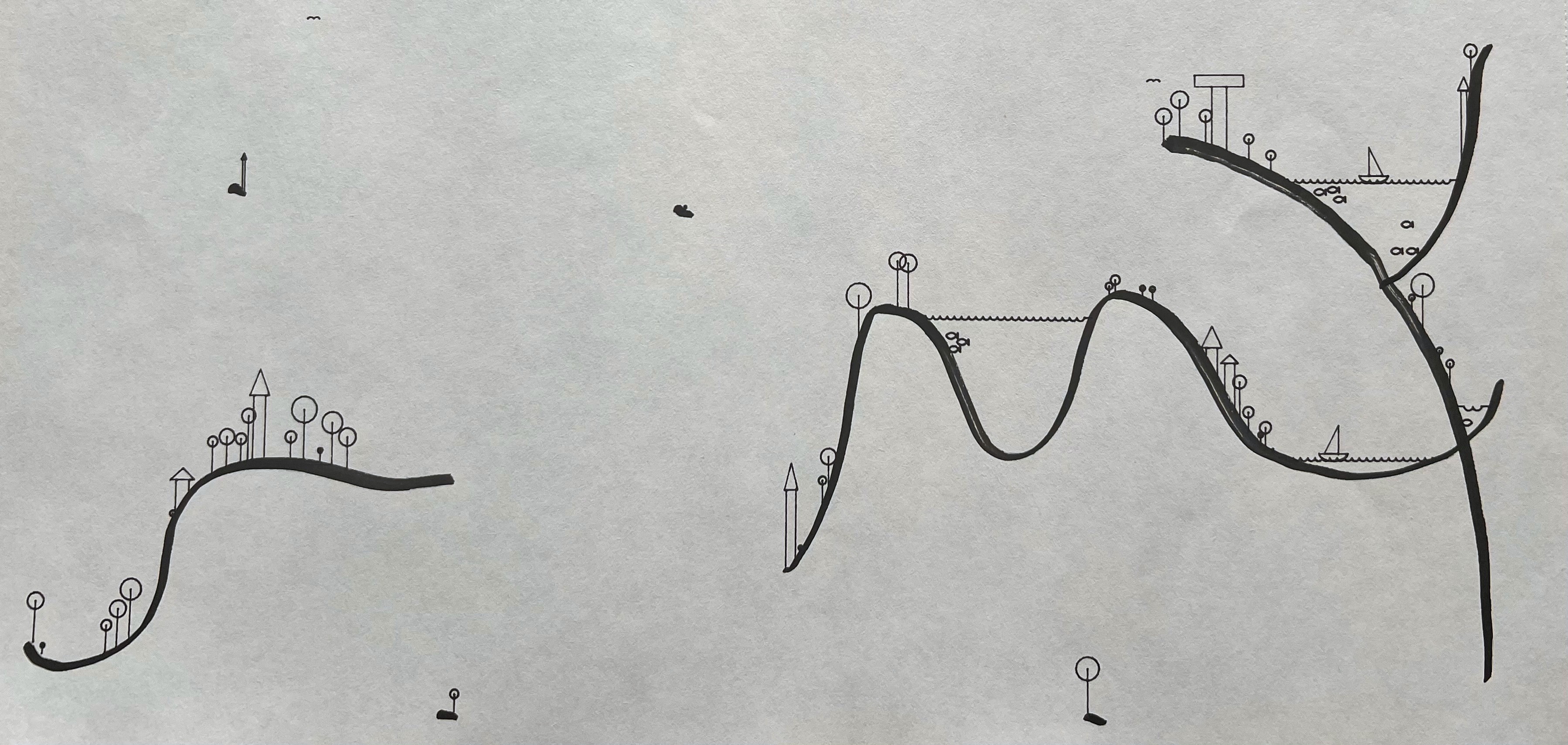
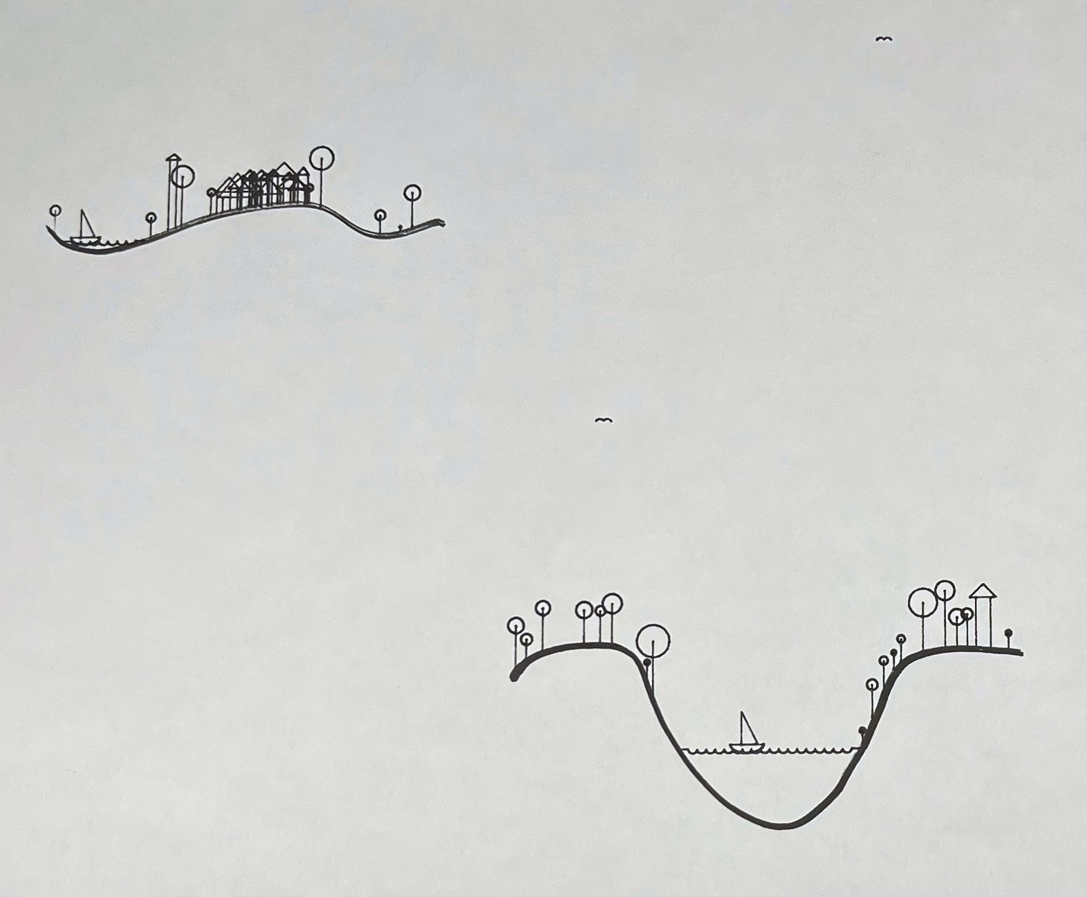
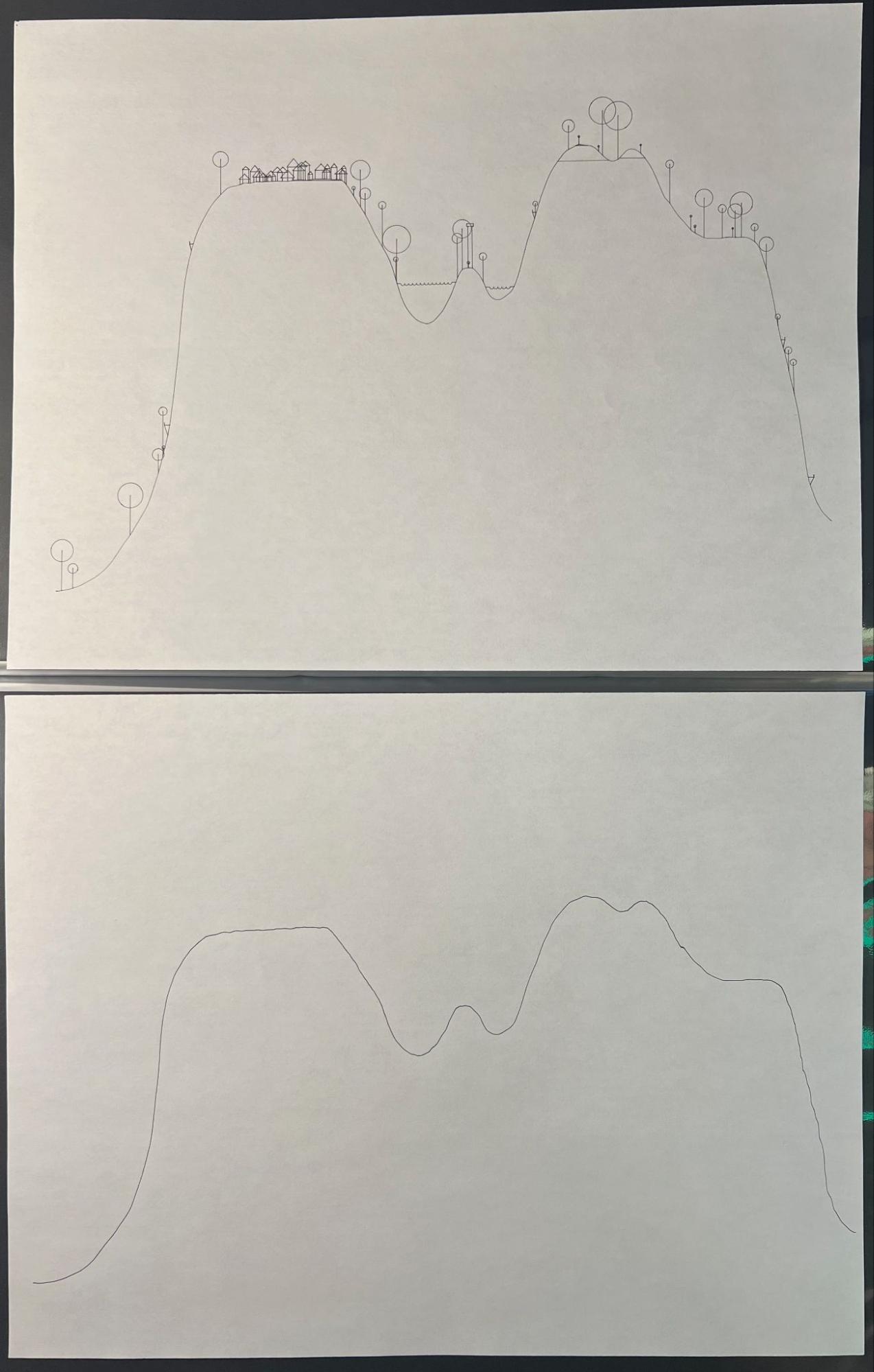
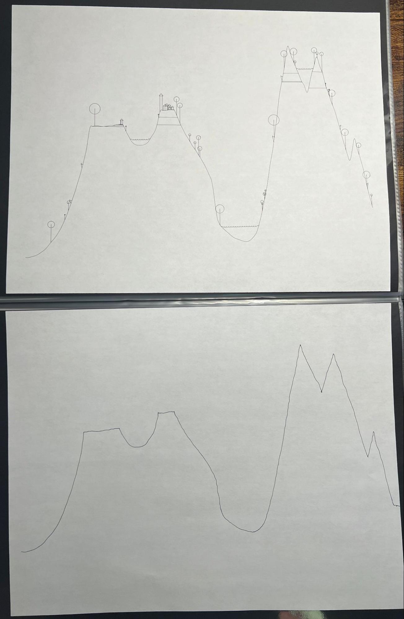
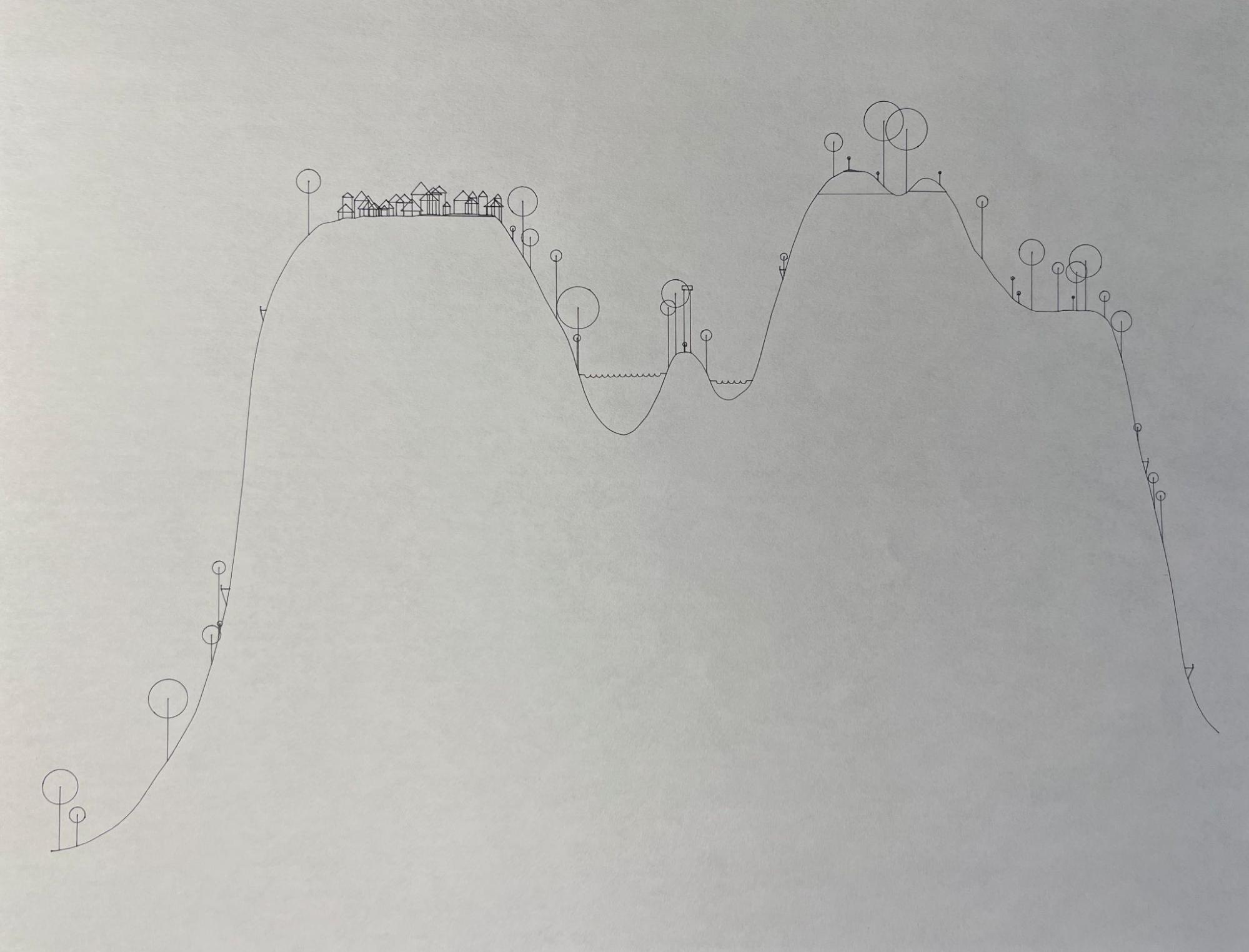
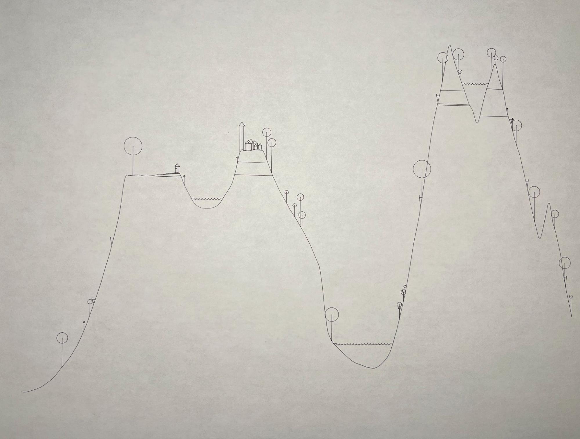
Within its more limited scope, it did work, leading to output like this - the machine’s reinterpretation on one sheet, the participant’s original line on the other:
The Second Prototype
May 2024
The second prototype was the final project for the same Drawing with Machines class. This time I had the better part of a month to create something that aligned better with my vision for the project. I made a video update showing where the project stood at this point:

Drawing in place
This was the first time I truly tackled the in-place goal, and with it the alignment issues I had ducked in February.
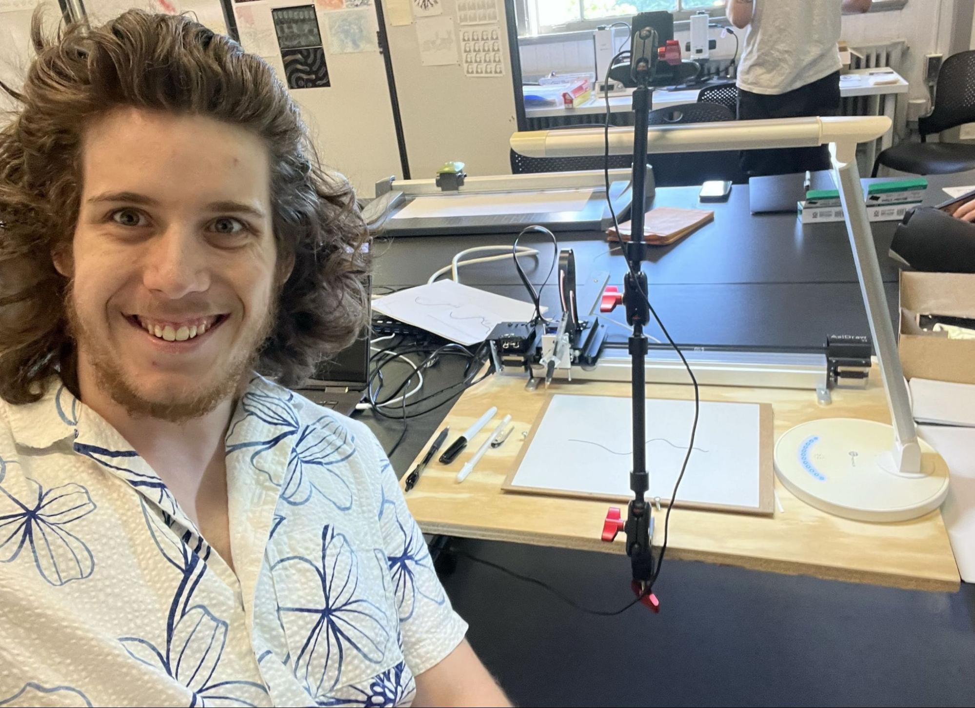
I kept the rig absolutely minimal for this version. I attached my computer’s webcam to an adjustable arm and cantilevered it directly over the working area of my Axidraw, camera pointing down. This meant the collaborator could draw their stroke and then place their drawing in front of the Axidraw. The webcam could see the piece of paper, and since the relative positions of the webcam and the Axidraw were known, a single photograph was sufficient for the Axidraw to know where to draw in order for the doodles to align with the hand-drawn line.
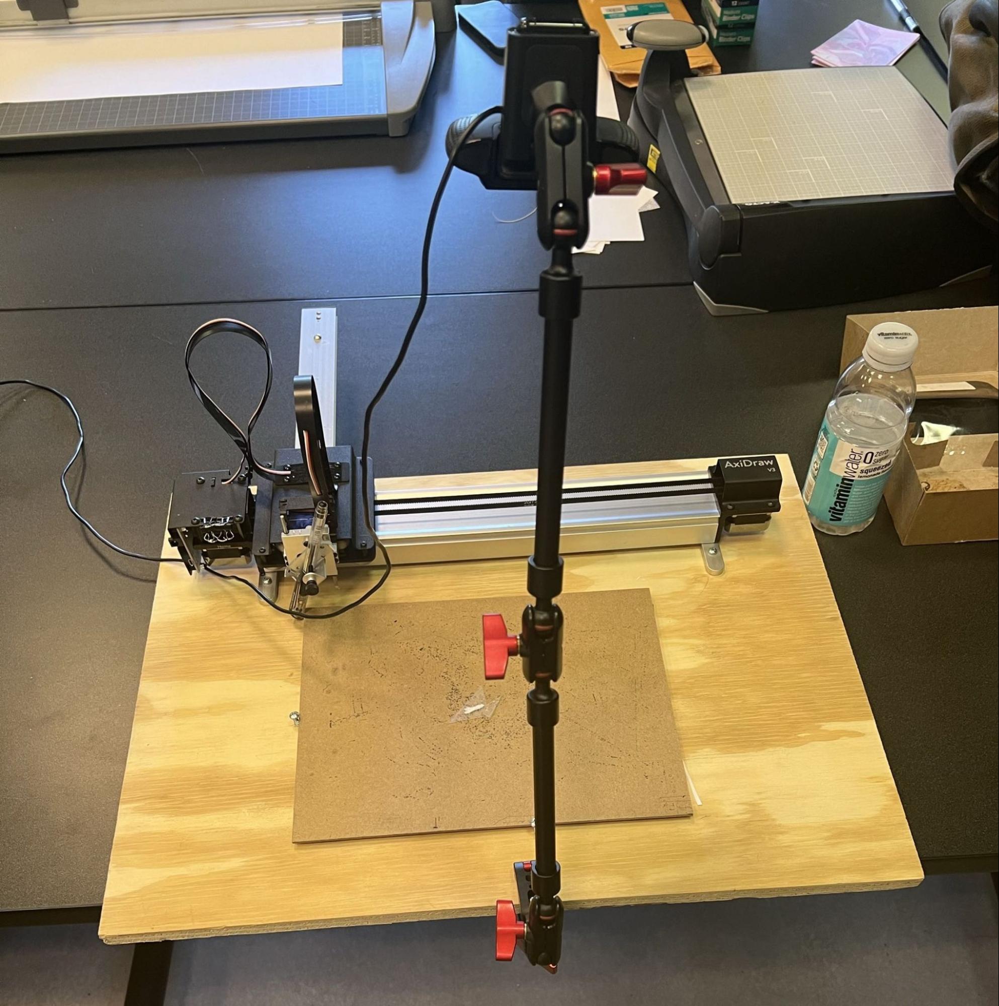
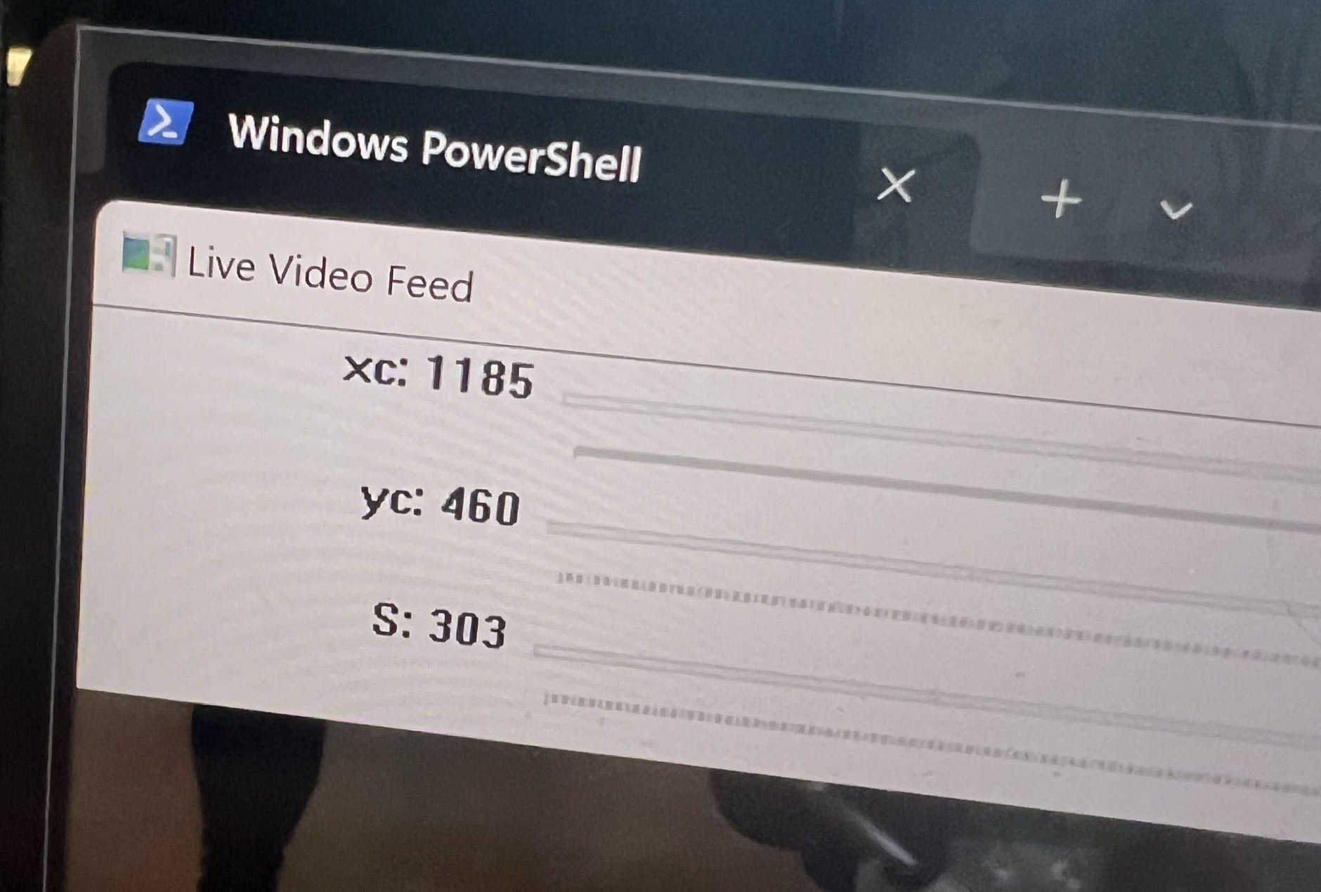
Alignment was handled in terms of three parameters, tuned live on trackbars: xc, yc and S. The image taken by the overhead webcam uses the image width as its unit while the Axidraw works in millimeters by default, so S is the constant scale factor converting screen width to millimeters. xc and yc set the zero point, aligning the top-left corner of the image with the corresponding location in the pen plotter’s working area.
Limitations of the minimal rig
I did not take lens distortion into account at all, so I calibrated this system for the center of the page; the further from that center point I got, the less accurate the alignment would be.
I could partially offset this by having the collaborator draw with a thick pen, which gave the plotter a larger target to hit without the drawings floating above the page. However, this only worked in one direction, and there is an interesting asymmetry here. It is better to have the doodles slightly too low than slightly too high. If a doodle is floating even a fraction of a millimeter above the page it is immediately obvious that something is wrong - a tree should not be levitating off the ground. The opposite is not quite so true: if a tree is partially embedded in the ground, it just looks like a slightly shorter tree. This effect is not consistent across all doodles, but it is useful enough that I began purposefully lengthening my doodles with the intention of the bottom half-millimeter being sunk into the line, giving myself a small margin for error in either direction.
Finding the line properly
I also improved the line detection system. Instead of finding the darkest pixel in each column, it now used OpenCV edge detection to find the contour of the line.
This is a more complex task than you might initially expect, because edge detection gives you the outline of the line - a very long, thin closed shape that encircles it - rather than a linear sequence of points. Converting that closed shape to a line is known as medial axis transformation (MAT), or centerline extraction, depending on which field you are in, and it is used for everything from mapping the layout of veins in the human body to extracting road data from satellites.
To make the transformation somewhat easier on myself, I maintained the same function requirement I had in the previous version. At this point I was still imagining the project as having the human participant understand ahead of time that they were helping to create a landscape, not just an arbitrary scribble. In the context of drawing 2D topography these limitations make sense: landscapes don’t tend to roll back on themselves or self-intersect - in fact such geometry is not physically possible and is quite hard to describe. It was only later that I moved toward having the human collaborator draw anything at all, and for that to be reinterpreted as a landscape after the fact.
Nonetheless, moving over to edge detection was an improvement. It removed two specific concerns. Absolute darkness detection was highly sensitive to shadows and tiny dark specks, and edge detection is not nearly so fragile. And lines no longer had to span from one edge of the frame to the other - since we are no longer scanning every vertical column, it is fine if there are columns the line doesn’t extend to.
The function requirement also makes the transformation far, far simpler. For full MAT you would usually reach for an existing package, such as scikit-image’s skeletonization. With the function limitation in place, you can find the centerline like this:
1. Let’s say you have this hand-drawn line that you want to process:
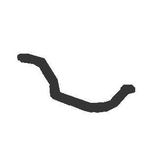
2. Naively, edge detection gives you this closed outline:
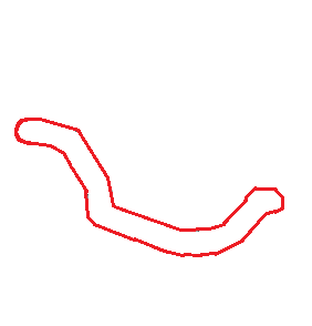
3. Now, since you know that the original line is a function, you know that one end of the line is the leftmost (smallest-x) point on the outline, and the other end is the rightmost (largest-x) point. Separating the closed outline into two lines at those two points leaves you with an upper contour and a lower contour. This is the step enabled by the function requirement.
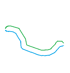
4. Find the average y value between the two lines for each x value. The last step guarantees that both contours share the same range of x values, and this is clean because the function requirement disallows any overhangs in the line.
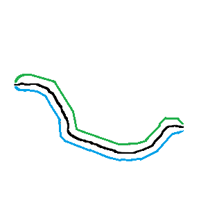
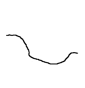
5. You’re done - this new y-averaged line is the centerline for your drawn line. Strictly speaking it approximates the medial axis rather than computing it, since the true medial axis is equidistant perpendicular to the stroke rather than vertically, but under the function constraint the difference is negligible.
Placing the doodles
I also improved the logic for how doodles were placed. The location of every doodle is determined before plotting begins, because there are certain logical rules they should follow. A lake must always begin and end at two points of equal elevation, with every point of elevation in the range of the lake lower than the elevation at its two endpoints. Trees and houses cannot exist within the range of a lake. Birds can only show up above the stroke, never below, and can appear as individuals or as part of a flock. Towers have an increased chance of spawning at the top of hills, and an increased chance of being tall there.
At this point the vocabulary of doodles was: birds, lakes, boats, houses, towns, towers, trees and altitude striations.
Results
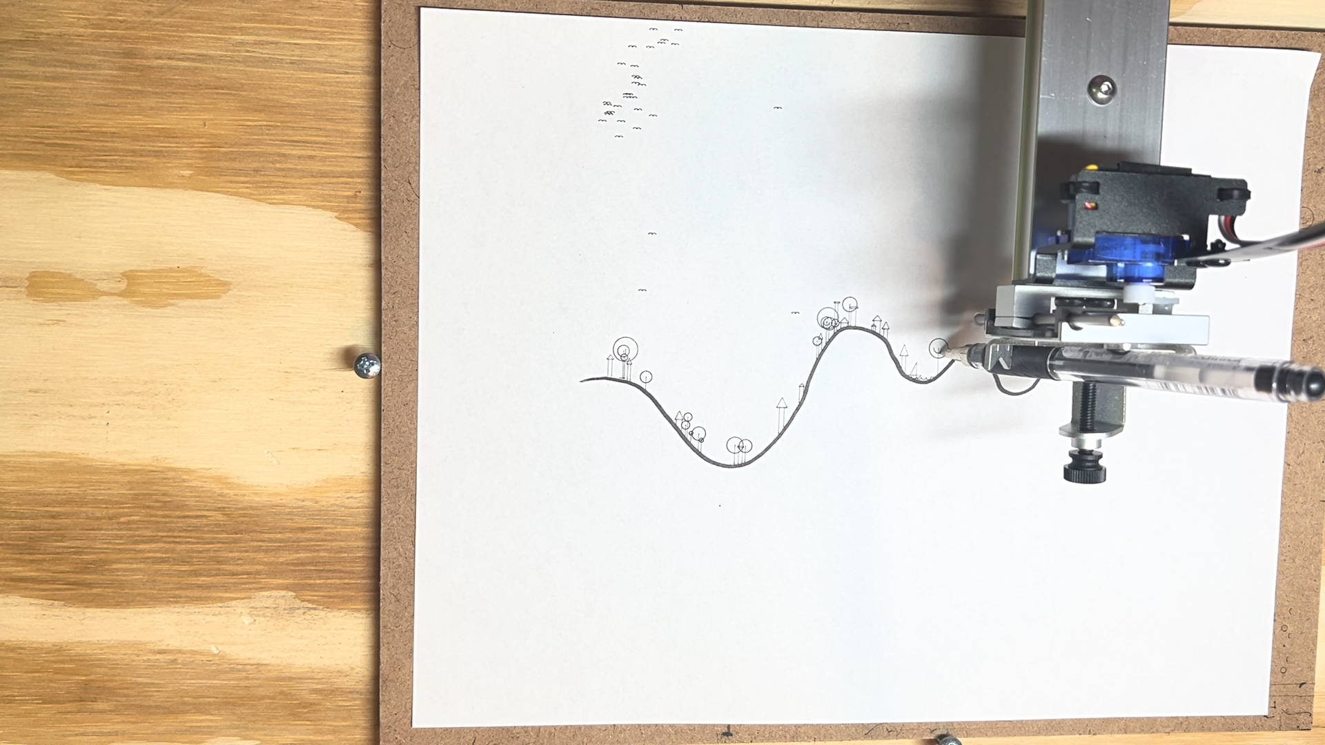
The final project demo was a success. The system worked correctly, and after explaining the limitations on what types of lines it could process, almost every person in the class was able to create and take home their own custom collaboration.
The Grant, and a Change of Scale
September 2024 - April 2025
Over the summer I worked on applying for the Frank-Ratchye Further Fund for Innovative Artworks so that I could continue working on the project beyond the scope of the Drawing with Machines course, and received the grant in September 2024. You can still find the finished project on the website of the Studio for Creative Inquiry, the organization that distributes the award.
Work then paused for several months while I focused on a series of other exhibitions and on my master’s applications, picking back up in earnest in early 2025.
With the money from the grant, I planned to dramatically improve the robustness of my system and turn it from a demo that could work for a few hours under my direct supervision into an installation that could run for weeks completely autonomously. This was quite the challenge given the numerous moving and electronic parts, plus the requirement of computer vision. I had a deadline of the end of April 2025, when it would be installed as part of the Rapid Eye Movement (REM) exhibition at the Tomayko Foundation, which ran through May.
A camera chosen for the job
The biggest single improvement was purchasing a webcam suitable for the task. Up until this point I had been wrestling with my auto-focusing computer webcam. Auto-focus is great for picking up faces in a video call as the user moves around, but terrible for calibration, where even slightly different focal lengths change the scale and warping of the image.
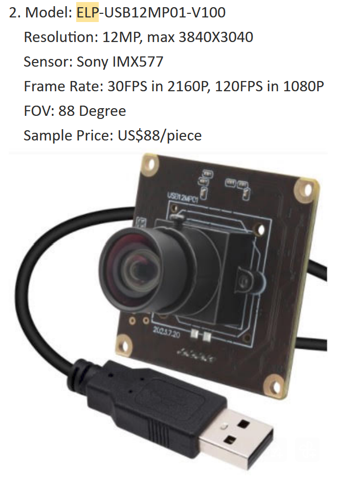
I bought the ELP-USB12MP01-V100 for a few particular characteristics that make it good for my specific computer vision task.
High resolution - 12MP, 3840×3040. I don’t need a super high resolution shot of the stroke drawn by the collaborator. What the resolution buys me is distance: it lets me place the camera further away from the drawn stroke and still get a decent resolution across the whole paper. Placing the camera far away matters because the narrower the field of view within which the paper exists - which is equivalent to moving the camera further away - the less lens distortion there will be. High resolution, in my case, is equivalent to low lens distortion.
Minimal lens distortion. It’s impossible to get rid of distortion entirely, but this compounded with the previous point was enough to render lens distortion negligible and remove the need to account for it mathematically.
No auto-focus, for the reason above. Auto-focus makes it impossible to consistently calibrate for the camera’s image.
The specifications that were not a priority are just as relevant. I only take occasional still pictures, never high-framerate video, and I am photographing something stationary - a sheet of paper on the Axidraw’s working bed. So a fast frame rate wasn’t important, and neither was a global shutter; a rolling shutter was perfectly acceptable. Being able to sacrifice those two things while keeping the resolution I actually needed drove the price down considerably.
Holding that alignment steady
This is distinct from the problem above: even initially very precise alignment can drift over time or be affected by bad conditions.
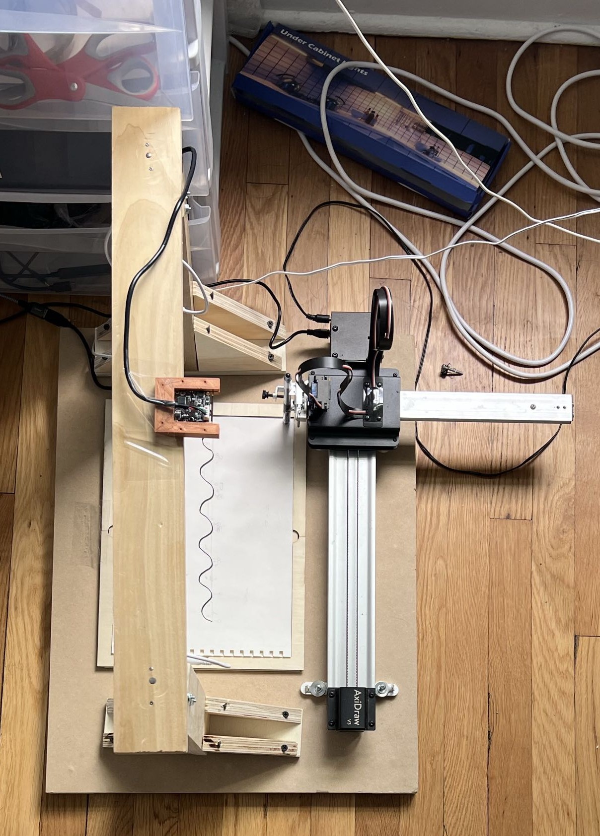
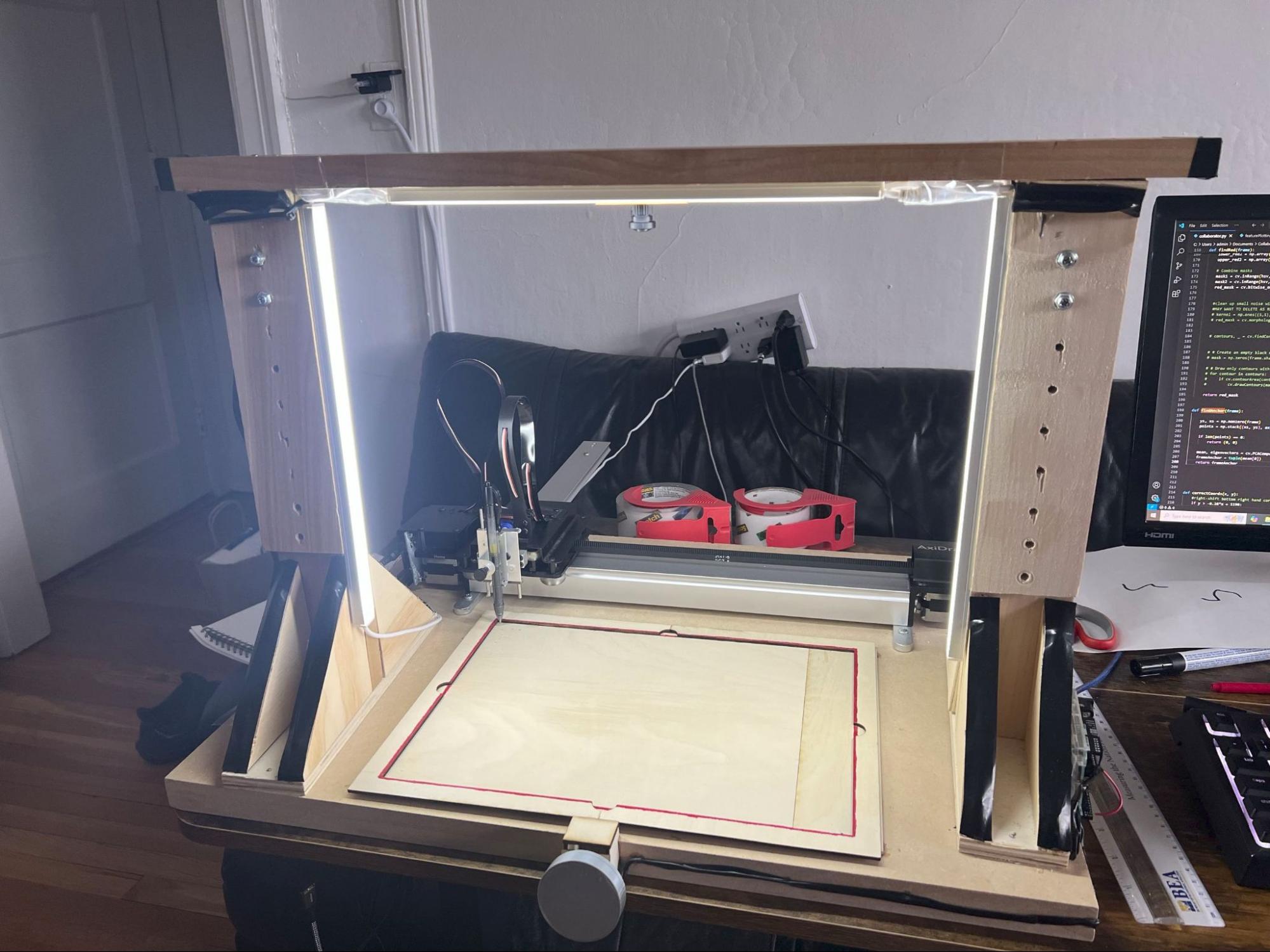
The previous system of holding the camera in an adjustable arm is clearly a problem. The arm, by nature, is capable of moving, so even when tightened it drifts over time. I replaced it with a wooden platform which bridges over the working bed of the Axidraw and is secured to the same base plate as the Axidraw on both sides. The camera is then mounted in much the same position as before, underneath the middle part of the bridge. This structure is extremely secure and will not naturally settle into a different position over time.
Standardized lighting
To overwhelm the natural variation in ambient daylight, I installed two sets of very bright lights directed at the working bed. For these lights, the important thing is to buy flicker-free ones. Many LEDs are actually pulsing at 100-120 Hz, twice the mains frequency, rather than emitting steadily.
The familiar problem with flickering light is in video, where the frame rate of the recording and the rate of the flicker interfere with one another. I am not recording video, though - I take single still pictures. The flicker is still a concern, but for a different reason, and the reason is the rolling shutter I chose in order to keep the camera cheap.
A rolling shutter does not expose the whole sensor at once. It exposes one row of pixels at a time, sweeping down the frame, so different rows of a single photograph are captured at different moments. Under a light pulsing a hundred times a second, rows captured at the peak of a pulse come out bright and rows captured in a trough come out dark, and a single still image ends up striped with light and dark bands. This effect has a name: banding. A high-resolution sensor makes it worse, since the slower the sweep down the frame, the more flicker cycles get laid across the image.
For a pipeline that decides what is land and what is sky by thresholding on brightness, bands across the frame are precisely the wrong kind of noise. Thankfully, you can buy effectively flicker-free lights relatively cheaply.
Letting people draw anything
I also wanted to improve the flexibility of the system. Specifically, I wanted collaborators to be able to draw anything they wanted rather than being limited to single function-like strokes. That also raised a new issue that appears with overhangs: the tops of doodles clipping into other parts of the line above them.
The new pipeline I built is designed to turn a line that is not a function into a series of lines that are. A hand-drawn squiggle is an arbitrary closed shape: it can double back on itself, have vertical cliffs, or enclose holes. But the doodle generator needs to walk left to right and ask, at each step, “where is the ground here, and how much clear space is above it?” That question only has an answer if the ground is single-valued. This pipeline, sitting between the raw image and the doodle generator, exists to carve an arbitrary blob into pieces that each answer that question cleanly. Where the second prototype had gone looking for the middle of the stroke, this one stops caring about the middle entirely and goes looking for its top.
It gets there in five steps:
1.Deciding what counts as land. Every pixel darker than a threshold is land, everything else is sky. That alone would give a ragged result, because the drawn stroke may have pinholes, broken edges, and gaps where the ink thinned out. So two cleanup passes run before anything else: one fills any empty pixel that is surrounded on three or more sides, the other closes small gaps by dilating and re-eroding (morphological closing). The line-finding step that follows works purely on pixel adjacency, so a single stray hole in the middle of a stroke would register as a piece of sky with its own floor and ceiling, and a one-pixel break in an edge would sever a line in two. Sealing the shape first is what makes the rest of the process trustworthy.
2.Splitting into separate lines. The cleaned map is then split into separate lines, where a line is defined as any group of land pixels connected to each other. Each line is an island in its own right, and lines smaller than five pixels are dropped as noise. From here every island is handled independently.
3.Finding the tops. Within an island, the top edges are found by simply keeping every land pixel that has no land directly above it and deleting all the others. This works with overhangs, because it doesn’t assume the island has one top. A blob that arches over a hollow has an outer top and, further down, the floor of that hollow is counted as a lower top. Both of them pass the test, because both have open sky immediately above. So an island with an overhang naturally yields more than one candidate surface.
4.Chaining them into surfaces. These remaining surface pixels are then sorted left to right and chained into lines. Starting from the leftmost unused pixel, the algorithm looks one column to the right for another exposed pixel within ten pixels vertically. If it finds one, that pixel joins the line and becomes the new reference point, and the chain creeps rightward one column at a time. Exposed pixels in the same column that don’t qualify are left alone, to be picked up later as the start of a different line. The chain ends the moment there is nothing available in the very next column within that vertical range. The process then restarts on whatever pixels are left over, until every exposed pixel has been claimed by some line. What this produces is a set of continuous, sloping, single-valued runs. The ten-pixel tolerance is our definition of “traversable”. When a blob’s edge rises or falls faster than ten pixels per column, the chain simply stops and a new one begins wherever the edge levels out again. Fragments too short to hold a feature get thrown out, so a near-vertical wall just renders as bare rock.
5.Giving every surface a ceiling. For each point along a surface, the column above it is scanned and the lowest edge of any land overhead is recorded - or the top of the image, if the sky is clear. Each line therefore arrives at the doodle stage paired with a matching height limit at every one of its points. Subtracting one from the other gives the headroom, and that is what lets a tower under an overhanging island be automatically shortened instead of drawn straight through the rock above it. The cave floor found back in step 3 gets a low ceiling here, so features placed on it come out small and tucked in - which is exactly the behavior you’d want, and none of it is special-cased.
To see this in practice, look at this sequence of pictures.
1. Let’s say you have these hand-drawn strokes:
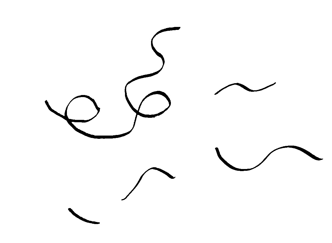
2. The pipeline organizes these strokes into a series of surfaces paired with their respective ceilings. Each island - equivalent to a stroke - is one color; each surface detected on an island is a one-pixel-thick layer along the top of it; the free headroom above a surface is another color; and the ceiling for each surface is another one-pixel layer directly at the top of that headroom.
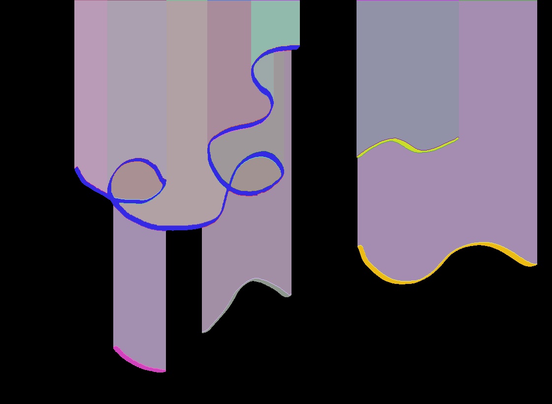
3. Finally, this is enough information for the doodle generator to know where it can place doodles and how large those doodles can be:
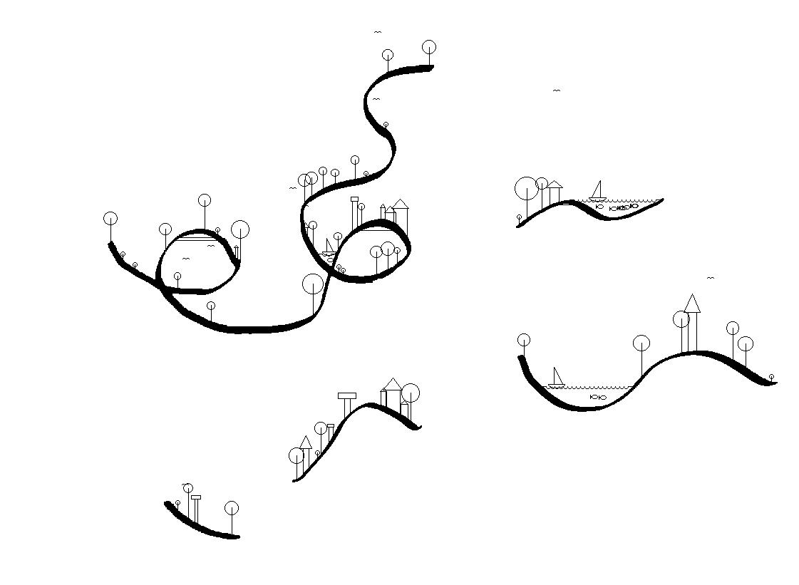
Fish joined the vocabulary of doodles around this time as well, swimming in the lakes alongside the boats.
Building for a Room I Wouldn’t Be Standing In
April 2025
Everything above makes the system better. The remaining work was making it survive without me - closed-loop automation and resilience, so that it doesn’t need to be reset between uses and can survive glitches in the system. This is very important, because the system was expected to be working all day, every day, for about two weeks in an exhibition setting. So I layered multiple levels of error catching where possible, and wherever possible made the system recover from a glitch without needing to cancel the entire collaboration.
At the highest level, if something goes wrong anywhere in the process - a bad camera frame, an unexpected shape in the drawing, a hardware stutter - the error is caught and logged rather than allowed to kill the program. The system then tears everything down, waits ten seconds (enough time for the Axidraw’s arm to home itself), and starts itself fresh.
An error-triggered restart is a full reset, not a patch-over. Before starting again, the machine tells all its background work to stop, waits a limited time for it to finish (so a jammed process can’t hold everything hostage), disconnects the camera, sends the pen back to its home position, and closes its connections to the plotter and to the begin-collaboration button. Each of those shutdown steps is handled independently, so if the camera has already vanished from the system, the pen still gets homed properly. This same full reset runs when one collaboration ends and the next begins, to prevent any issues from accumulating over time.
The plotting itself happens in the background, separately from the camera and display. This means the live view stays responsive while the pen is working - which is otherwise a blocking process - and the operator’s key commands are still heard mid-drawing. The system also knows when it’s busy: pressing the start button again while a drawing is underway is simply ignored.
The system checks for a stop signal constantly on its own thread, between every feature it draws and repeatedly while tracing long lines. This stop signal is what the system uses to jettison a collaboration if an unrecoverable error happens. When it stops, it lifts the pen and returns it home instead of freezing mid-stroke, so the Axidraw does not lose track of its home location, as it has no sensor for finding it again. After an interruption it also discards any keypresses that were mashed during the pause, so a stale command doesn’t fire once things resume.
Individual features are insulated from each other. Every individual doodle is drawn inside its own protective wrapper: if one of them fails for any reason, the machine notes the problem, confirms that the pen is lifted so it doesn’t drag ink across the page, and simply moves on to the next feature. A single bad element costs only a single doodle, not the whole collaboration.
There is also a ceiling on how long any one drawing can take. Before anything is plotted, the machine counts up how many features it is about to draw. If that number is too high, it throws the plan away and generates a sparser version of the same landscape. This keeps each collaboration to a reasonable length and prevents an unusually dense or complicated input drawing from tying the machine up for hours and stalling the queue.
Finally, the whole vision and geometry pipeline is written without the assumption that users will create a valid drawing. When the camera can’t detect a usable stroke, or the stroke is too small, too short, or too cramped to hold a feature, the system simply does nothing and reports that there is no valid line. Specks of noise get filtered out, gaps in detected lines are tolerated, and features are continually nudged and clamped so they stay on the paper and don’t collide with the terrain above them. The result is that imperfect input - a faint pencil line, a smudge, a drawing near the edge of the page - produces a slightly simpler picture rather than a failure.
An interface that explains itself
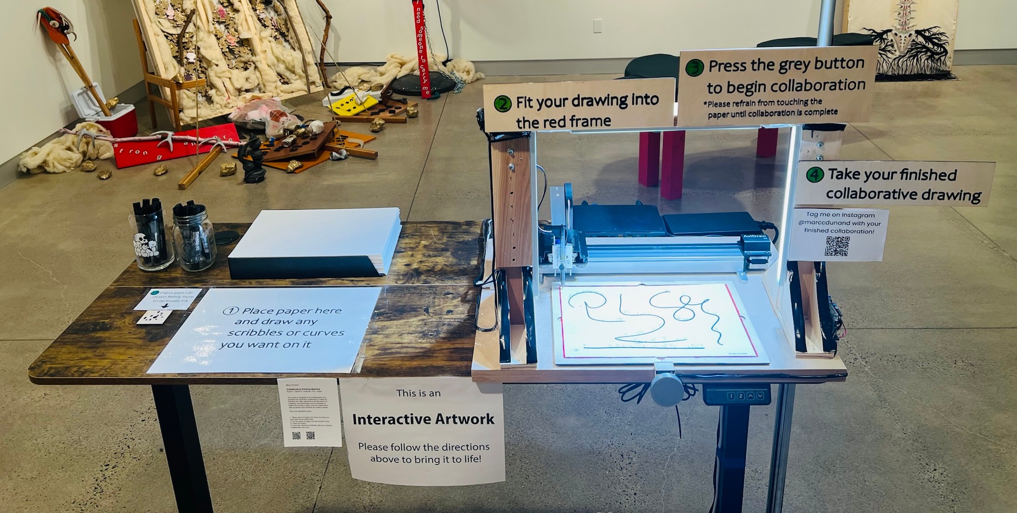
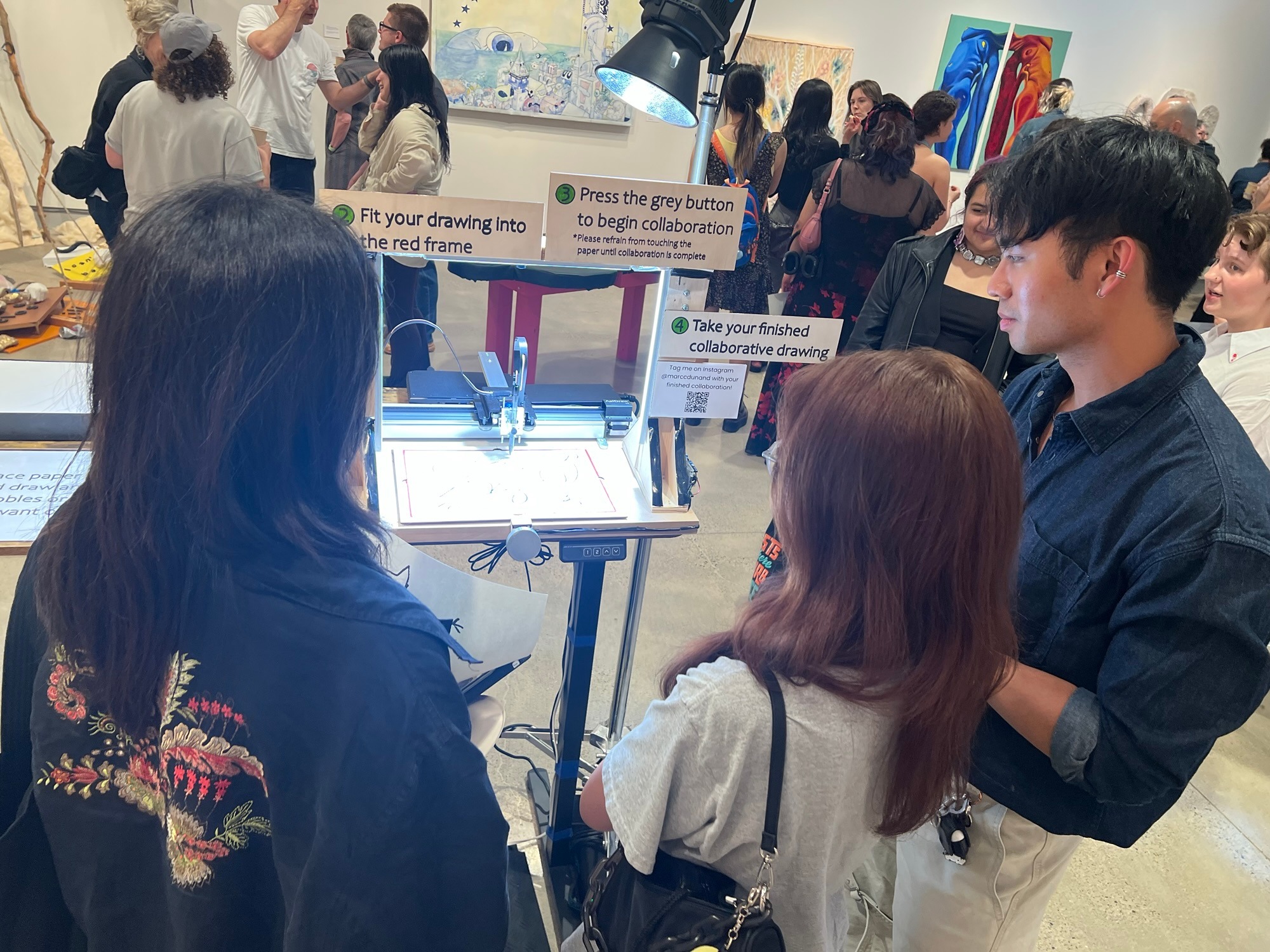
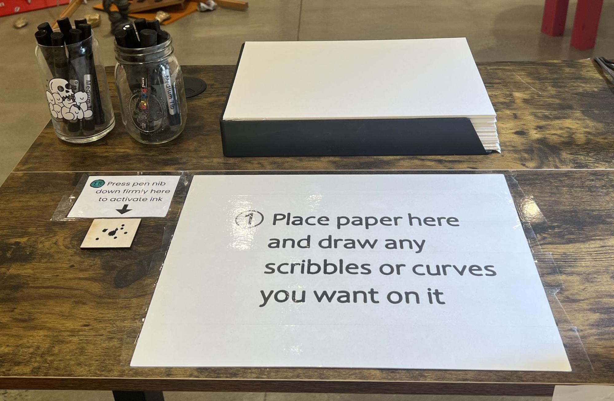
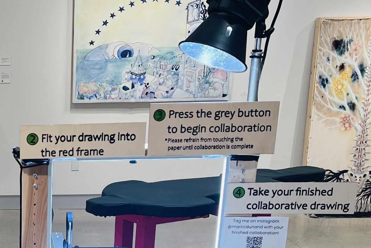
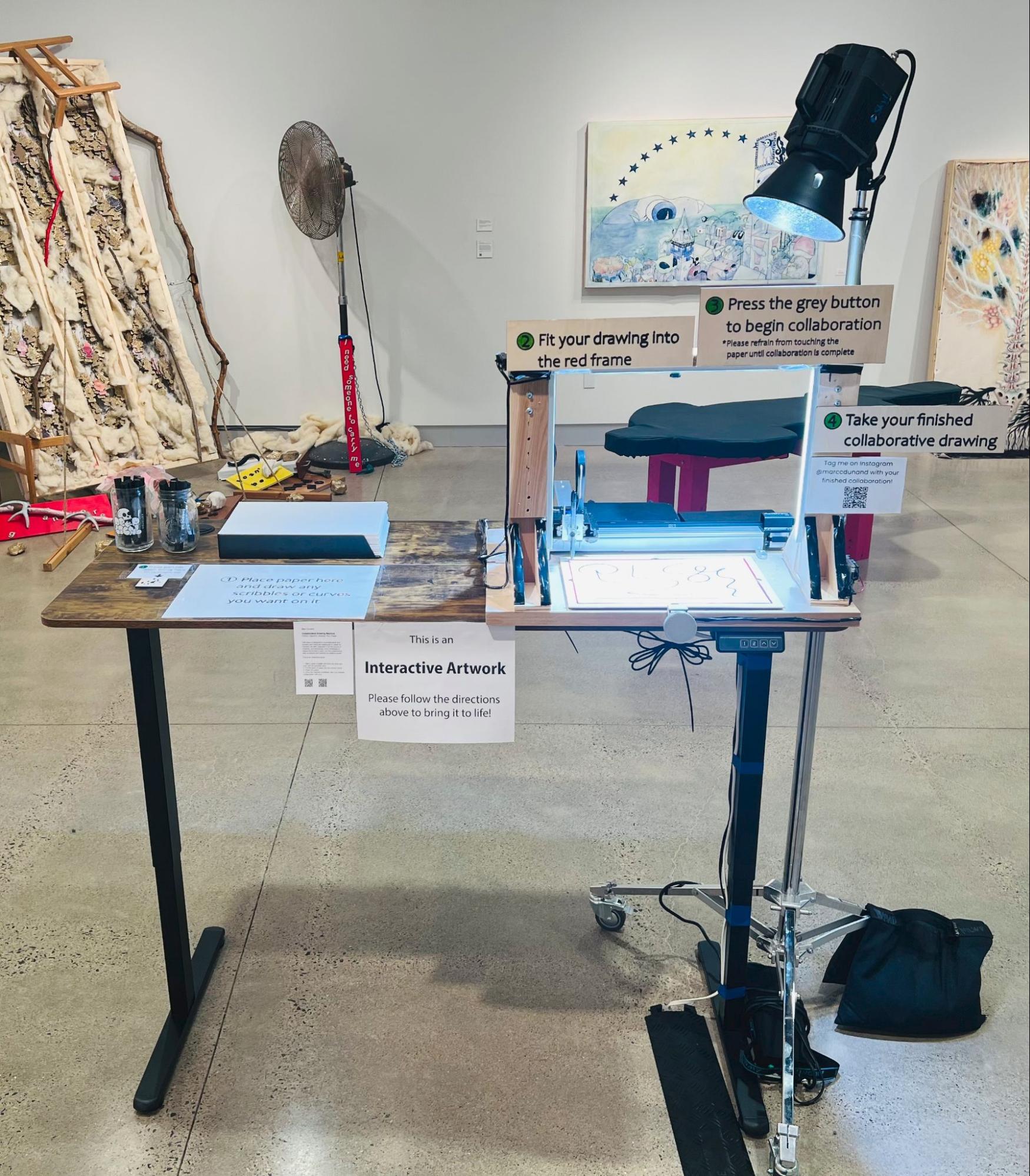
As much as the Tomayko Foundation has a gallery attendant who can answer questions for gallery-goers, I wanted my piece to speak entirely for itself. I built the final installation so that users would move through the collaboration from top left to bottom right. Starting at the top left corner, you pick up pen and paper. Then, below that, you create your drawing. Then to the right, you place your drawing on the working bed of the Axidraw. Then to the right of that, you take your finished drawing home with you.
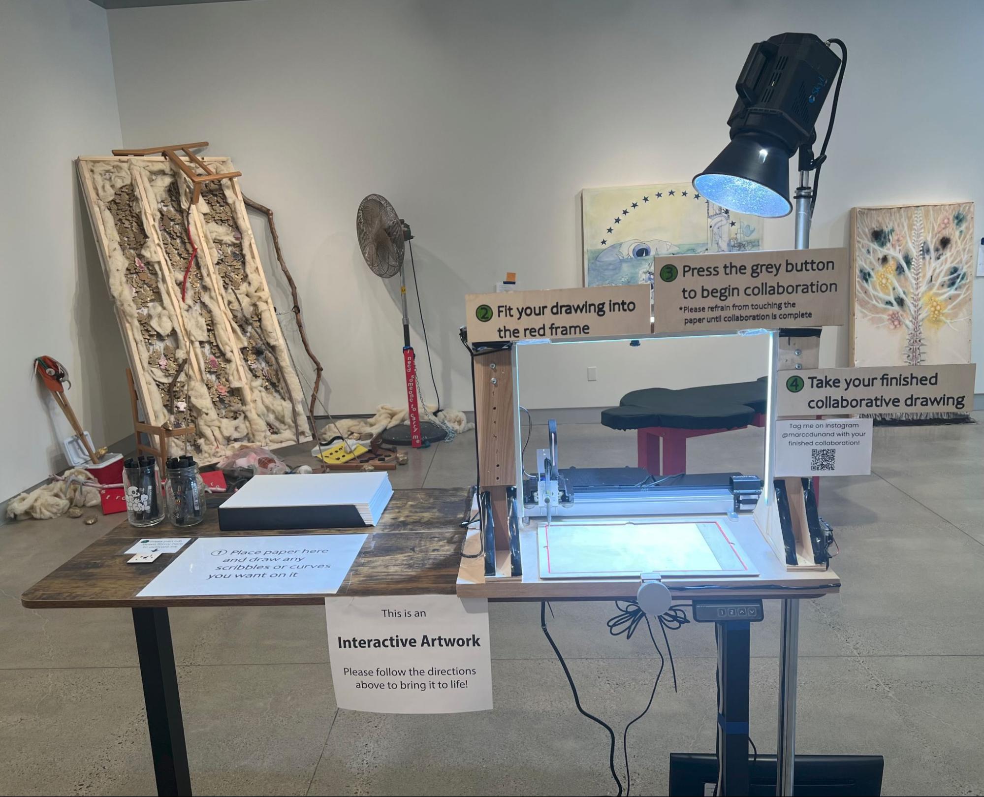
Each of these steps was also explained with a plaque. The plaques are laid out left to right in the same order and have the same visual language throughout - green circled numbers for each step.
One button
Up to this point, starting a collaboration meant pressing the spacebar on my laptop. That is fine when I am standing next to the machine, and useless in a gallery: a keyboard invites a visitor to press the wrong key, and a visible laptop makes the piece read as a computer demo rather than as a machine.
So I gave the installation exactly one control - a single gray button, wired to an Arduino that sits between the button and the main program. The Arduino watches the button and reports its state to the main program over a serial connection, and the main program listens for that on its own dedicated thread. That threading is what makes the button feel immediate: a press registers straight away without interrupting the live camera view or whatever the plotter happens to be doing, and because the program already tracks whether a collaboration is in progress, pressing the button mid-drawing does nothing at all.
The reason for the button is that it reduces the entire interface to a single unambiguous action. There is exactly one thing a visitor can do, it is labeled on a plaque directly above it, and it cannot be done wrong. That is what turns the piece from a demo I operate into an installation that operates itself.
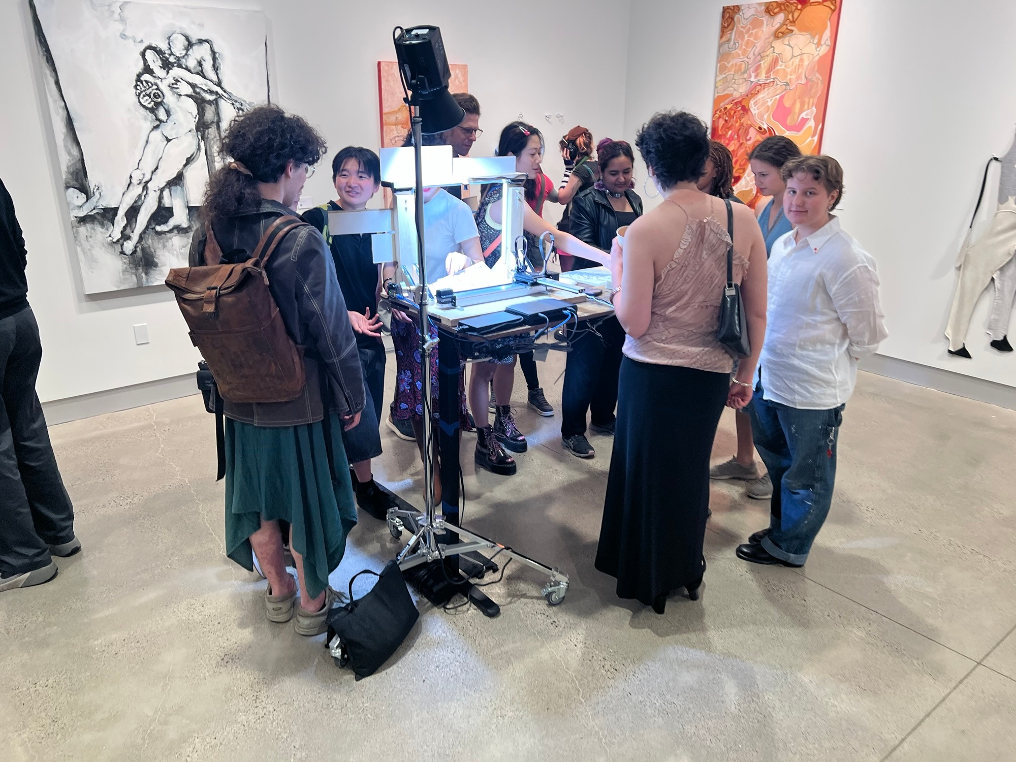
A handful of small fixtures were laser-cut to hold the rest of it together: a pen holder, a housing for the button, a frame for registering the paper on the bed, borders and wooden backings for the plaques, and a pincher for priming the ink.
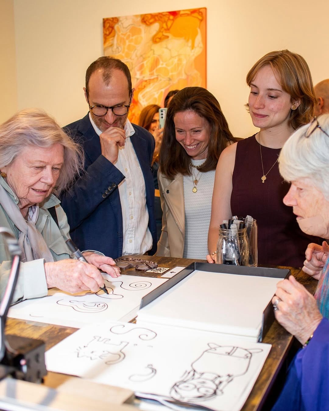
With all of these changes, plus improvements to the presentation and cleanness of the whole layout, the finished installation looked like this:
What It Became
May 2025
Collaborative Drawing Machine took a little over a year to go from a weekly class assignment to an autonomous gallery installation, and almost all of that time was spent closing the gap between two sheets of paper and one.
The first prototype could only read a line that was a mathematical function, photographed under careful lighting, and could only answer it on a separate sheet - which made the collaboration real but kept the collaborators apart. The second prototype put the human and the machine on the same page for the first time, by fixing a camera above the plotter and by replacing darkest-pixel detection with edge detection and a centerline. It still asked the participant to draw something landscape-shaped.
The final version asks nothing. You draw whatever you want - loops, crossings, overhangs, several separate strokes, a scribble that means nothing at all - and the machine works out for itself where the ground is, how much sky sits above each piece of it, and what belongs there. Then it draws directly onto your paper: trees, towers, towns, lakes, boats, fish, flocks of birds, altitude striations. It runs on one button, recovers from its own failures, budgets its own drawing time, and did all of that for two weeks at the Tomayko Foundation without needing me in the room.
What I set out to test was an assumption: that in a collaboration between a person and a machine, the person supplies the creativity and the machine supplies the labor. The finished piece inverts it. The human takes the simple, nearly mindless job of drawing a line, and the machine does the imagining - nondeterministically deciding that this particular curve is a shoreline, that this hollow is a cave, that this hilltop should have a town on it. Every visitor left with a drawing that neither collaborator could have made alone.
The full source code for the project, along with the CAD files for its laser-cut parts, is on GitHub.